"DaviSumIt" TB-5©™ "Mic-All" Amplifier / Mixer
"On-Line Manual" - Applications Data
Certain concepts and terminology copyright © 1986-2006 by DaviSound
As part of our 2006 "WG" expansion ...
the TB-5 was redesigned for the larger 3RU layout to allow
for more space on the aesthetically pleasing "WG" control panel.
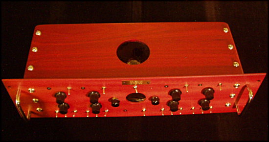
As is typical with all "WG" units, there is no front panel lettering to detract from the solid, woodgrain appearance. All controls are obvious to the experienced user and the following layout is offered as a familiarity reference.

At the top of the panel, traditional DaviSound phantom powering is provided with a discreet, isolated phantom power feed, independently switchable and LED monitored, supplied to each channel.
The uppermost rotary pot is the fully variable, active gain control for the MP-2 "Mic-All" preamp MasterPiece circuit module.
Just below the gain control, a low impedance panpot routes the signal from the individual channels to either Left or Right sum outputs, or anywhere "in between", in typical panpot fashion. DaviSound panpots are designed so that maximum action occurs nearer the CCW / CW extremes of the pot wiper rotation. This is so that "center" settings are easily repeatable, with channel balance maintained, as adjusted by the individual left / right output master controls.
At the bottom of the control panel, below each channel section, is a cluster of three toggle switches. The first switch, vertically mounted, is the direct/mix switch. With this toggle in the "down" position, the preamplifier output is routed DIRECT to the rear output jack for the respective channel. When the switch is in the "up" position, then the channel is in the "mix" mode and routed to the stereo mix busses via the panpot.
The second, vertically mounted, toggle switch below each channel segment controls a first order 6 dB per octave Hi-Pass filter with appoximate action as follows:-6dB at 100HZ, and -12dB at 50HZ and minus 18dB@25Hz. Switching the toggle to the UP position activates the filter, whereas the bottom position by-passes the filter.
Just to the right of the Lo Cut filter switch is the horizontally mounted phase reverse switch.
The left/right phase reverse action of the respective phase switches is all relative of course but the LEFT toggle position corresponds with input pins 2 & 3 to output pins 2 & 3, whereas the RIGHT position reverses the polarity of input pins 2 & 3.
Approximate gain control settings for the MIC-ALL microphone preamps, as determined by the white pointer position on the control knob, are as follows:
The TB-5 mix bus is hand-wired and configured using the same innovative techniques of ALL DaviSound mixers pioneered many years ago in early DaviSound designs. DaviSound mix-busses are NOT configured on Printed Circuit Boards with thin, parallel traces and the inherent problems associated with those methods utilized in commercial mixers!
Instead, DaviSound employs multi-paired, twisted-pair bus wiring techniques similar to those now recently being utilized in manufactured "quad cables". However, our hand fabrication and controlled placement of the routing of these busses within the mix stages offers superior noise rejection and combined, lowest capacitive loading effects which are not achievable by other methods!
In addition to this unique mix bus technique, the new TB-5 "WG" also introduces an "Inner Tube" option with the inclusion of the all new ...
"MPT-1" (MasterPiece Tube Module) circuit block configured as a unity gain, inverting summing amplifier!

The new MPT block features a hardwood circuit board ...
with all circuit components mounted underneath ...
rigidly embedded in thermal epoxy.
The boards are mounted on one half inch rails for a slightly
elevated position above the cabinet floor.
The first ever MPT used in the first ever TB-5 shown above ...
is made form quilted African Mahogany for a touch of the "exotic" on the inside!
A very nice "floor mount" for the 6SN7 octal tube!
The MP-1 based master output section offers approximately 6 dB of additional through mixer gain to the Mic-All preamp stages with the UNITY gain setting ocurring at approximately 12 O'Clock, with the master control knobs' white pointers in the "straight-up" position. The gain controls of the master stage are just that ... ACTIVE gain controls which offer the same benefits as the active gain controls for each individual stage, as described below.
The additional mix-amp output driver stage of the TB-5 adds negligible noise and distortion to the Mic-All amplifiers as opposed to using the individual stages alone through their own outputs-certainly none that is audible. However, since EVERY stage in any design has to, inherently, add some degree of THD plus noise, measurements of those parameters at the sum outputs will be marginally higher ( about .002% additional THD + Noise combined).
The "Inner Tube" stage in the TB-5 , with the 6SN7 octal packaged dual triode, is in/out switchable and, while configured for unity gain via negative feedback, there is about a 1 dB reduction in level with the tube switched in, as opposed to through the MP-1 sum amp direct, due to low impedance loading effects acting on the tube stage. Although the tube is operating with less plate supply voltage than normally associated with vacuum tube circuitry, the headroom through the Class-A triodes is still respectable at +18 dBU! Since the MPT-1 block is configured as a unity gain inverter with "virtual ground" summing junction very simlar to the MP-1 "op-amp" summer it drives, THD is VERY low compared to traditional tube circuitry and measures under .01% with the tube switched in!
The tube may be selected by flipping the "tube switch", the mini toggle centered just above the control panel center port hole, to the "right" position. Switching to the "left" position completely by-passes the tube stage.
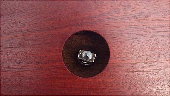
The tube may be removed for replacement by carefully reaching inside the "firehole".
Grasp the tube top between the thumb and forefingers and gently rock it back and forth
while lightly pulling in an upward motion until it works free of the socket.
Either a 6SN7 may be used, as shipped, or a 6SL7 can be employed
for slightly differing performance.
The inaugural TB-5 was the first to use the 2 1/2 inch diameter, now standardized, top access port ...
which seems to be the ideal size for the opening.
A unique feature of the TB-5 ...
and other DaviSound Tool Boxes ...
which employ sensitive circuitry, such as mix busses, within a necessarily close proximity to the power supply ...
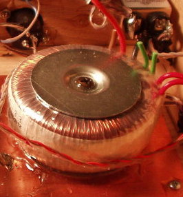
is the Toroid style power transformer.
Toroidal coil winding techniques tend to eliminate external EMI radiation from the power transformer keeping hum fields internal within the Toroid core "do-nut".

The XLR outputs are 100 ohms "quasi-balanced" as per DaviSound Tool Box standards with PIN 2 HI and PIN 3 LO. For balanced operation, shields are ground and, according to traditonal schools of thought, should be connected at ONE END only. This, of course, assumes that at least one shield of the multiple connections offers a direct ground to the associated equipment. In practice, leaving shields connected at both ends will probably work as well but, theoretically, shields work better when they do NOT carry current.
For unbalanced operation from the XLR outputs, use only PIN 2 (IGNORE PIN 3) and the shield which, for unbalanced use, should be connected to connectors at both ends of the cable. Or, preferably, two conductor plus shield cable should be used with the one conductor to PIN 2 (IGNORE PIN 3), the second conductor to PIN 1, and the shield connected only at one end to PIN 1!
The AC power cord IEC EMI FILTER RECEPTACLE and FUSE HOLDER are at the far left of the rear panel.
PERFORMANCE -
Performance "DaviSpecs" Specifications
Unless specifically stated otherwise in individual descriptions ...
and for all Tool Boxes which employ our "MP-2 MasterPiece" circuit module, which is nicknamed the "Mic-All", for the complete signal chain gain block, the electrical specifications are as follows:
ALL amplifiers feature ruler flat frequency response ...
with -3dB points at 1.6 HZ and 35 KHz (maximum gain). There is a slightly variable HF bandwidth increase as gain is actively decreased to unity or below
(flat to 70KHz at unity).
This is because an active filtering configuration is employed to intentionally rolloff extreme high frequency response to minimize RF / EMI out of band interference, noise contribution, and intermodulation distortions.
Combined distortions specifications are where the DaviSound "MIC-ALL" amplifiers REALLY outperform most all others anywhere! There is virtually NO measurable distortion at any level or frequency until maximum gain settings are utilized. Even then, the measurements are near the residuals of the test instruments and barely detectable at the frequency extremes- (.008% at 20 KHZ, +55dB gain)!
Under more reallistic gain settings, amplifier distortion is even lower (example: typically .001%, 1KHZ, 40dB gain ... immeasurable at gain settings below 40 db [theoretically, mathematically indicated better than .0008%] )!
This performance characteristic is responsible for claim after claim from virtually ALL awe inspired users that our amp is the "cleanest" they have ever heard!
One of the most crucial parameters in microphone signal handling is HEADROOM. The MIC-ALL amps are relatively unsurpassed in this regard with signal handling capability right up near +32 dBU before clipping! We acheive this with our House IC and thermal protection which allows a much higher power supply voltage than most conventional designs. This provides a full 8 to 10 dB more headroom than many other professional designs on the market today!
Keep in mind, that output level offered by an output boosted stage does NOT always correspond to system headroom throughout! Some other units boast an output of +36 dB, or more, that do NOT offer that headroom throughout their chain. DaviSound specs are through chain, input to output.
EIN Unweighted -122dB 100 ohms
Noise 20Hz to 20KHz Unweighted - 98dB
Actual internal impedance is 2KOhms, differentially balanced for optimum voltage transfer of all low impedance professional microphones from 50 ohms impedance to 600 ohms impedance.
Actual output impedance is 100 ohms (47 ohms unbalanced) and the high current "Mic-All" output stages will drive virtually any line load from 600 ohms to high impedance bridging with no increase in distortion or any other loading effect!
ELECTRICAL SPECIFICATIONS FOR DAVISOUND HOUSE IC USED IN "MIC-ALL" MP-2 "MasterPiece" Modules |
The inherent specifications of the House IC itself are actually further enhanced in our actual audio application by our circuit design techniques within the MP-2 module!
One such technique ... which we believe has so much to do with the exceptional, noticable "accuracy of detail" comment that we hear so often from users in regard to the performance of our amplifiers ... is a unique inter-stage direct coupling/biasing scheme which forces the amplifier into near full Class-A operation. Any extra heat generated in this process is harmlessly dissapated in the thermally conductive epoxy ecasement of the sealed MP-2 module!
This, combined with the, overload proof, fully variable, active gain technique, produces results as close as you can get to a truly "distortionless" amplifier!
|
NOTE:
While the "Mic-All" preamp offers up to near 60 dB of gain, keep in mind, as can be seen from the chart below, that such extreme settings are very seldom needed! Typical maximum studio mic preamp gain requirements are around 40 dB or less on the average.
Some interesting observations in regard to actual microphone output levels and, thus, resulting amplification requirements -
Here is an enlightening study, done some time ago, and published in Audio Amateur Magazine on several occasions (original- Russell Hamm - JAES 21:4 [May, 1973] ) in regard to audio signal levels measured direct FROM MICROPHONES.
Please note that the measured levels we are talking about here are STRAIGHT out of the microphones themselves with NO additional amplification!
This will surprise most all but the most experienced, veteran recording engineers since, in some cases as will be shown, you would not only NOT need ANY mic preamplification but might even need gain reduction!
Peak Mic levels 0dB ref to 0dBu=.775 volts

INSTRUMENT        Distance in inches    Neumann U-87               RCA-77DX           EV-666
                                                         (Typical condenser)           (Ribbon)            (Dynamic)

 Bass Drum                     6                         0                                 -9                      -4

 Large Tom Tom              12                       -1                                 -9                      -5

 Small Tom Tom              12                       -1                                 -7                      -1

 Piano (single note)           6                       -25                               -38                    -32

Cow Bell                         12                      -10                               -29                    -15

Loud Yell                         4                         0                            Not Tested             -10
Notice that a loud yell (or similar loud vocal musical note!) into a typical condenser mic can produce an unamplified output of 0 dBU which is .775 volts RMS or about 2.2 volts peak to peak!
On the other hand, it is not uncommon to encounter, say with a "whispery" female vocalist into a ribbon mic, even as close as three inches, signals as low as -50 dBU or about 7 millivolts!
So, a microphone preamp has to, quite literally, deal with one extreme to another.
The MIC-ALL preamp can, as structured in the TB-6, typically output +28 dBu with some headroom.
However, if set for a gain of, say, 40 dB...it can be seem from the above examples that it would easily overload and distort with many of the microphone signals shown!
At that setting, a loud yell or vocal extreme into a condenser mic at about six inches could cause the amp to try and pass a +40dBu signal ...obviously at LEAST 12 db past the clipping point! Obviously, the higher you raise your "0 VU" operating level, the LOWER your headroom before the clipping stage!
That is the point of the INFINITELY VARIABLE GAIN CONTROL that allows you to continually "dial-in" just the right amount of gain for your incoming microphone signal!
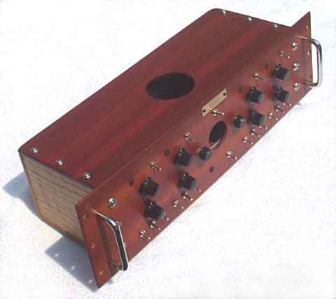
The inaugural TB-5 was made with exotic Padauk faceplate ...
exotic Bloodwood cabinet top ...
and traditional Red oak side rails, rear panel and bottom.
For more photos of the inaugural TB-5 "WG" 3RU ...
CLICK HERE
The rack cabinet itself is made from hand sculptured SOLID, natural wood. As of spring 2001, we have opted for lustrous, hard penetrating oil finishes for the cabinetry as this provides added protection for the wood and, unlike other oil finishes, it is relatively maintenance free. Simply wipe it with a soft dry cloth to restore lustre. The front and rear panels are treated with extra coatings of acrylics for added protection.
"WG" Models, such as the new TB-5, are entirely made of wood! The front panel as well as the rest of the cabinet are ALL solid oak (unless other exotic woods have been utilized by client arrangement/preferance). Like all natural things, every piece of wood has its own, distinct character and "personality". This makes EACH AND EVERY "WG" model unique unto itself which enhances the aesthetic value of the piece and the actual appreciative monetary value as well!
Keep in mind that as part of this wood "character" it is impossible to find/utilize a "PERFECT" piece of wood. This means there may be slight imperfections, or variations, in terms of grain pattern, color uniformity, and skew. However, any such natural variations in our selected pieces are very minor and are the very thing that gives wood its charm and "character" appeal!
Aside from the tube, accessible through the 2 1/2 inch top access port, there are NO user servicable parts inside the TB-5. DaviSound Tool Boxes are fashioned from our "Master
Pieces" modules which employ hand-laid circuitry, silicon embedded into plastic cased modules.
In the unlikely event that service should ever be required, simply contact us for return
authorization and we will replace the defective module(s).
While never having been enforced, it was original DaviSound policy to void warranties if the top cover is removed! However, certainly be advised that ANY internal tampering or unauthorized repair or modification attempts void all warranties!
NOTE:
NEVER ATTEMPT TO REMOVE THE FRONT PANEL, REAR PANEL OR BOTTOM PANEL OF ANY TOOL BOX AS THEY ARE NOT REMOVABLE AND ANY ATTEMPT TO DO SO WILL DESTROY THE CABINET!
DaviSound products are carefully assembled BY HAND, one piece at a time from start to finish,
in prototype assembly fashion, with extreme care and attention. They are designed to perform
from now on with no trouble.
However, there are always "real world" imperfections that can not be anticipated or accounted for no matter HOW careful one might be in fabrication. For example, we don't make the ICs, we don't wind the power transformers and we don't construct the pots and switches. No matter how well you select and screen, these things can fail at times. Ours seldom do, due to extensive testing and pre shipment "burn-in" periods, but if you should ever have a problem, you are protected for as long as you own the equipment, as the original owner.
Simply carefully repack the unit in the original packing, ship it back to us (after notification) to
DaviSound, 1504 Sunset Ave., Newberry, SC 29108 803-276-0639
and we will repair and reship at no charge to you whatever!
Thank you for your purchase and use of a DaviSound Tool Box!
And, we also thank you for allowing us to go these "extra lengths" within YOUR operating manual to elaborate in accordance with our "mission" in publishing these on-line manuals. It is all part of an ongoing effort to provide as much educational material as possible from this website in the sincere belief that ...
The more one truly KNOWS about audio electronics, the more one can truly appreciate the DaviSound methods!
We thank all of you who ALREADY know all of this covered herein for your indulgence as we present it for those who do not!
Please let us hear from you regarding your application of our unit and feel free to contact us with any questions or comments throughout the future!
We also hope that you will consider ALL of the DaviSound Tool Box models for your rack!
THANK YOU and GOOD LUCK!