DaviSound TB-7
"DaviStrip"
Single Channel Multi-Processor
Copyrights 1998-2008, 2010 © by DaviSound


The TB-7 "DaviStrip" Revised and Re-introduced March, 2008 in Custom Cabinetry
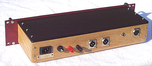

The Long awaited "DaviStrip" now provides several of our most sought after audio tools in one convenient package for the serious amateur recordist, project studio owner or professional remote recording / broadcasting media.

The "DaviStrip" Package includes ...

  1. The "Mic-All" Preamp Stage with Mic / Line-Instrument Switching
  2. Separate Rear Panel Line input with dedicated Front Panel MIX control
  3. The "Musi-Q" Four Band Equalizer with associated In/Out Switch and LO-CUT Filter Switch
  4. The FET Version of the "DaviSmart" Compressor with Release Select Switch, In/Out Switch and Gain Trim
  5. Optional Remote DC Power Supply / Battery Operation capability


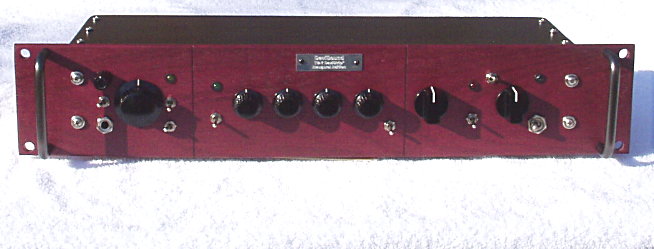
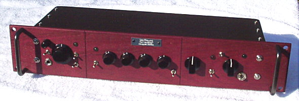
The TB-7 is supplied with three different knob styles for distinct visual indication of the three stages.
Actual knob stylings may vary depending on availability or client special order preferance.

The illustrator model shown is client special order cabinetry ...
Purpleheart Faceplate, Wenge Top and Oak Cabinet


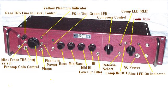
The various stages are presented in logical order beginning with the preamp ...
followed by the equalizer, and then the compressor / line driver stage with gain trim.
The signal flow follows this same sequence as the panel layout.


Note that the TB-7 offers DUAL Male XLR, output jacks.
The outputs are "quasi-balanced" as per DaviSound Tool Box standards with PIN 2 HI and PIN 3 LO.

However, instead of the typical 100 ohm output impedance of most standard Tool Boxes, the divided outputs of the TB-7 are isolated 600 ohms.This provision is so that a disturbance, or even a short, across the load of one output will have negligible, or no, affect on the other output. This is a highly desirable feature for live remotes!

These multiple output feeds are provided as a convenience for remote broadcast and recording as well as for use as a main/monitor, or similar applications, in-house.

For unbalanced operation from the XLR outputs, use only PIN 2 (IGNORE PIN 3) and the shield which, for unbalanced use, should be connected as ground at both ends of the cable.


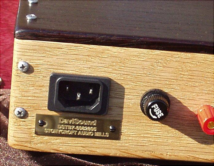
As of 2007, it was decided to begin adding remote DC power capabilities to certain, applicable Tool Box models. The new TB-7 is one of these models! To facillitate BATTERY OPERATION when required for remote, field use, THUMBSCREW TERMINALS coded red (+) and black (-) were added to the rear panel.

Note that the BLACK screw terminal could also serve as a supplemental direct ground terminal where desired in rack installations.

Any user supplied battery pack with a standard DC voltage of 12 volts to 44 volts may be utilized. Naturally, headroom and maximum output capabilities are closer to specifications with the higher supply voltages. However, professional results can easily be acheived with supplies of 18 to 36 volts and most traditional condenser mics will still function properly when phantom powered within this lower voltage range as well.

While care should be taken when connecting a remote power supply since main on/off switching is by-passed in this mode, the TB-7 is internally protected against accidental power supply polarity reversal.

Please note that the front panel main on/off LED indicator (green) will light when the battery supply is connected. However, the main power switch (AC on/off) does not function when powered by remote, battery supply.

This would also be an opportune place to mention that the Main power indicator LED, on most Tool Boxes including the TB-7, does NOT turn off instantly when power is removed! There will be a decay, typically, of around thirty seconds or so. We mention this here since some users have actually thought something was "wrong" with their units because of this. Quite the contrary! This "hold function" delay is simply an indication of the superior storage capacity of the on-board power supply filter capacitors!

It is advisable to have the detachable AC power cord REMOVED whenever remote DC power is connected to the thumbscrew terminals since AC power should not be applied simultaneously with remote DC battery supplies connected to the unit!


As with all DaviSound Tool Boxes, the AC power cord IEC EMI FILTER RECEPTACLE and FUSE HOLDER are at the far left of the panel. .


"MIC-ALL" ™©

The first stage of this versatile processor is the original, highly acclaimed, DaviSound "Mic-All" ©™ preamplifier.

The microphone input is by rear panel XLR input connector. All of the controls are clustered to the far left of the front panel with the MIC-ALL active gain control to the center of the cluster.

The vertically mounted on/off switch located right of the gain control is the PHANTOM POWER on/off switch with up/down operation. An adjacent yellow LED indicates phantom power on/off.

Directly below the vertically operated phantom power mini-toggle switch is a horizontal mounted mini toggle switch.
This is the phase reverse switch.

The left/right toggle handle position phase reverse action of the respective phase switches is all relative, of course, but the LEFT toggle position corresponds with input pins 2 & 3 to output pins 2 & 3, whereas the RIGHT position reverses the polarity of input pins 2 & 3.


The left horizontal toggle position of the Mic/Ins switch selects the Rear XLR Microphone input for routing through the "Mic-All" preamp stage. The right position selects the front T-R-S- Instrument/line input jack for routing through the preamp stage at higher impedance, reduced gain structure. However, since the active gain stage offers proper, infinitely variable, matching to the source signal, the "DI" instrument input can also be used as an extra line input with variable gain when desired. In that case the control would need only to be "cracked" at about 8 or 9 O'Clock. Approximate gain control settings for the MIC-ALL microphone preamps, as determined by the white pointer position on the control knob, are as follows:

9 O'Clock = + 28 dB      12 O'Clock = + 48 dB     3 O'Clock = + 55 dB      Full CW = + 58 dB

The LINE - INSTRUMENT INPUT offers approximately 18dB LESS GAIN at each similar position of the control.

Using the front panel T-R-S line input jack as a direct injection for musical instruments offers a unique application for an instrument amp!

Instead of the typical UNBALANCED instrument inputs utilized on most preamps, the TB-7 employs a special impedance/gain adjusted version of the MIC-ALL amplifier block in its DIFFERENTIAL configuration.

This arrangement offers the extremely large low frequency Common Mode Rejection Ratio inherent to the MIC-ALL amplifier design (around 100 dB) and this results in extremely quiet instrument input operation with extremely high immunity to hum pickup!

Since the TB-7 only utilizes a single MP-2 module for the Mic/Instrument input functions, special multi-way switching was devised to select between the rear panel mic jack and the front panel line/instrument TRS jack and the latter's matching / support circuitry.

NOTE - The TRS front panel input functioning as both line buffer and instrument input is possible because the medium/high impedance of this input is perfect for terminating, or bridging, all low impedance, line-level signal sources. And, since the first stage in this switched mode operates at unity gain, the following fully variable gain stage makes for a perfect, completely variable gain, matching buffer amplifier although, for +4 dBU operating levels only very low settings will be required.


When dedicated unity gain line level routing is desired, the rear panel T/R/S jack should be used with it's associated front panel line level control. This allows line/mic mixing (or line instrument mixing as desired) or separate line level return of an effect if desired. The level control for the dedicated line input is located to the upper left of the alternate switchable preamp gain control. This line input is optimized for +4 dBU input level signals. 1 Volt RMS in will yield 1 volt at the outputs (unity gain) with the level control full CW and the output amp trim control centered at 12 O'Clock.

The Instrument and Line inputs utilize T-R-S jacks to offer additional instrument cable wiring options when mating with the differential inputs and each type accepts signals from balanced or unbalanced sources.


Performance "DaviSpecs" Specifications


Unless specifically stated otherwise in individual descriptions ...
and for all Tool Boxes which employ our "MP-2 MasterPiece" circuit module, which is nicknamed the "Mic-All", for the complete signal chain gain block, the electrical specifications are as follows:


  • FREQUENCY RESPONSE-
    ALL amplifiers feature ruler flat frequency response ...
    with -3dB points at 1.6 HZ and 35 KHz (maximum gain). There is a slightly variable HF bandwidth increase as gain is actively decreased to unity or below
    (flat to 70KHz at unity).

    This is because an active filtering configuration is employed to intentionally rolloff extreme high frequency response to minimize RF / EMI out of band interference, noise contribution, and intermodulation distortions.

  • DISTORTION -
    Combined distortions specifications are where the DaviSound "MIC-ALL" amplifiers REALLY outperform most all others anywhere! There is virtually NO measurable distortion at any level or frequency until maximum gain settings are utilized. Even then, the measurements are near the residuals of the test instruments and barely detectable at the frequency extremes- (.008% at 20 KHZ, +55dB gain)!

    Under more reallistic gain settings, amplifier distortion is even lower (example: typically .001%, 1KHZ, 40dB gain ... immeasurable at gain settings below 40 db [theoretically, mathematically indicated better than .0008%] )!

    This performance characteristic is responsible for claim after claim from virtually ALL awe inspired users that our preamp is the "cleanest" they have ever heard!

  • HEADROOM -
    One of the most crucial parameters in microphone signal handling is HEADROOM. The MIC-ALL amps are relatively unsurpassed in this regard with signal handling capability right up near +32 dBU before clipping! We acheive this with our House IC and thermal protection which allows a much higher power supply voltage than most conventional designs. This provides a full 8 to 10 dB more headroom than many other professional designs on the market today!

    Keep in mind, that output level offered by an output boosted stage does NOT always correspond to system headroom throughout! Some other units boast an output of +36 dB, or more, that do NOT offer that headroom throughout their chain. DaviSound specs are through chain, input to output.

  • NOISE -
    EIN Unweighted -122dB 100 ohms
    Noise 20Hz to 20KHz Unweighted - 98dB


  • IMPEDANCE-
    Actual internal impedance is 2KOhms, differentially balanced for optimum voltage transfer of all low impedance professional microphones from 50 ohms impedance to 600 ohms impedance.

  • ELECTRICAL SPECIFICATIONS FOR DAVISOUND HOUSE IC USED IN "MIC-ALL" MP-2 "MasterPiece" Modules

    Frequency response, (as-is, un-compensated, unity gain, .777 V RMS input ) ... flat to 10 MHZ
    Input Noise Voltage at 1KHZ - less than 4 nanovolts per stage
    Typical Supply current - 11 mA (maximum- at full gain- full load)
    THD plus noise at unity gain, per inverter stage less than .0002%
    Slew Rate 12 V/uS
    Maximum Supply Voltage + 48 volts
    Lifespan- unknown - absolute minimum expected performance ...
    under less than ideal thermal conditions - 20 years ...
    Typical expected performance under average operating conditions - 100 plus years ...
    Theoretical performance under ideal conditions - 1,000 years!


    The inherent specifications of the House IC itself are actually further enhanced in our actual audio application by our circuit design techniques within the MP-2 module!

    One such technique ... which we believe has so much to do with the exceptional, noticable "accuracy of detail" comment that we hear so often from users in regard to the performance of our amplifiers ... is a unique inter-stage direct coupling/biasing scheme which forces the amplifier into near full Class-A operation. Any extra heat generated in this process is harmlessly dissapated in the thermally conductive epoxy ecasement of the sealed MP-2 module!

    This, combined with the, overload proof, fully variable, active gain technique, produces results as close as you can get to a truly "distortionless" amplifier!

    Generally speaking, in regard to most performance specifications, DaviSound Tool Boxes perform better than any of the state-of-the-art equipment that is currently available to test them! This is why we say they offer the quality reference by which to judge all others.


    ABOUT ACTIVE GAIN CONTROL !

    The fully ACTIVE, continuously variable gain control of the "Mic-All" Circuitry design allows you to DIAL IN exactly the right amount of amp gain for a given application. Often this will be +20 to 30dB and seldom more than 40 to 50 dB as will be noted!

    Now, consider that when any amplfier operates with GAIN ...its NOISE GAIN also increases! SO, the actual NOISE contribution of a MIC-ALL amp or any other variable gain amp, is also VARIABLE depending on the actual active gain settings! This means, that you have a MUCH superior noise specification and actual performance with an ACTIVE gain control set for, say, 30dB of needed gain as opposed to a fixed gain amplifier of, say 40 dB of fixed gain with a simple PASSIVE attenuator added to reduce level!


    "MORE APPLES AND ORANGES" -

    "Wide-Open" on a volume control in front of a fixed 40dB gain stage is NOT the same thing as "wide open" on a variable gain control offering 58dB of gain - by FAR not the same thing! That is the whole POINT of and the whole beauty of operation with a VARIABLE gain control! ON the "Brand X" amp, with the "noise gain" always fixed ... all the "control" does is passively attenuate the signal! - (ORANGES!)

    Alternately, with our FULLY VARIABLE ACTIVE control, the amplifier GAIN STRUCTURE is fully variable from 0 dB to +58 dB based on the control setting whereby if, say, only 20dB of gain is needed on the mic amp, then as it turns out, the user would actually have about a 30dB lower noise floor, in that case, all other factors equal, than with "brand-X"! See the BEAUTY? - (APPLES!)


    NOTE:
    While the "Mic-All" input stage of the TB-7 offers up to near 60 dB of gain, keep in mind, as can be seen from the chart below, that such extreme settings are very seldom needed! Typical maximum studio mic preamp gain requirements are around 40 dB or less on the average.

    Also remember that an addtional 6 dB of semi-variable (trim) gain is provided by the line driver of the the final compressor stage.
    Some interesting observations in regard to actual microphone output levels and, thus, resulting amplification requirements -

    Here is an enlightening study, done some time ago, and published in Audio Amateur Magazine on several occasions (original- Russell Hamm - JAES 21:4 [May, 1973] ) in regard to audio signal levels measured direct FROM MICROPHONES.

    Please note that the measured levels we are talking about here are STRAIGHT out of the microphones themselves with NO additional amplification!

    This will surprise most all but the most experienced, veteran recording engineers since, in some cases as will be shown, you would not only NOT need ANY mic preamplification but might even need gain reduction!

    
    Peak Mic levels 0dB ref to 0dBu=.775 volts
    
    INSTRUMENT        Distance in inches    Neumann U-87               RCA-77DX           EV-666   
                                                             (Typical condenser)           (Ribbon)            (Dynamic)
    
     Bass Drum                     6                         0                                 -9                      -4
    
     Large Tom Tom              12                       -1                                 -9                      -5
    
     Small Tom Tom              12                       -1                                 -7                      -1
    
     Piano (single note)           6                       -25                               -38                    -32
    
    Cow Bell                         12                      -10                               -29                    -15
    
    Loud Yell                         4                         0                            Not Tested             -10


    Notice that a loud yell (or similar loud vocal musical note!) into a typical condenser mic can produce an unamplified output of 0 dBU which is .775 volts RMS or about 2.2 volts peak to peak!

    On the other hand, it is not uncommon to encounter, say with a "whispery" female vocalist into a ribbon mic, even as close as three inches, signals as low as -50 dBU or about 7 millivolts!

    So, a microphone preamp has to, quite literally, deal with one extreme to another.

    The MIC-ALL preamp can, as structured in the TB-7, typically output +28 dBu with some headroom.

    However, if set for a gain of, say, 40 dB...it can be seem from the above examples that it would easily overload and distort with many of the microphone signals shown!

    At that setting, a loud yell or vocal extreme into a condenser mic at about six inches could cause the amp to try and pass a +40dBu signal ...obviously at LEAST 12 db past the clipping point! Obviously, the higher you raise your "0 VU" operating level, the LOWER your headroom before the clipping stage!

    That is the point of the INFINITELY VARIABLE GAIN CONTROL that allows you to continually "dial-in" just the right amount of gain for your incoming microphone signal! This infinitely variable gain structure has much to do with why our preamps are preferred over those with fixed, or even switchable, gain settings with their inherent drawbacks.


    Also, keep in mind that the down chain stages in the TB-7 can add gain, including the equalizers and the final line driver stage!


    "MUSI-Q" ™©

    The second section of the TB-7 features our fixed, four-band "MUSI-Q" equalizer.

    This proprietary EQ circuitry has remained in our "arsenal" all these years since so many engineers and musicians swear by it as one of the "most musically useful", four-band equalizers ever conceived!

    Now using outboard, EQ controls harnessed to proprietary MP-1 circuit gain blocks, it offers LO and HI "shelving" combined with Lo Mid and Hi Mid "peak and dip" curves at approximately ... 50 HZ, 250 HZ, 2.5 KHZ, and 8 KHZ, +/- 15 dB.

    The LO SHELVING CONTROL is designated as 50 HZ which means this is the approximate frequency where the LO control reaches it's maximum effect.

    On the other hand, the HI SHELVING CONTROL is designated as 8 KHZ but this is the approximate frequency where this control BEGINS it's shelving action. The curve then swings upwards towards the upper extreme of the audio spectrum where the full 15 dB boost occurs.

    This final control has a built-in HI-Frequency rolloff (HI-CUT) that kicks in at the extreme boost settings (beyond THREE O'CLOCK) of the HI SHELVING CONTROL to prevent the boost of frequencies outside the audio band thus aiding stability while preventing inaudible, but existing, ultrasonic "garbage" to be boosted that could otherwise interfere with and corrupt the signal!

    So, unlike many other simple shelving equalizers, this one may be used at FULL BOOST without fear of supersonic overload and resulting intermodulation!

    The fixed MID BAND controls operate, as already stated, in a PEAK/DIP fashion and are centered with a MEDIUM "Q Factor" very close to the 250 HZ and 2.5KHZ respective frequency ranges.

    Many "harsh/hard" low mids have been "softened" with a gentle cut of the " LO MID" control of this equalizer on many recordings over the years!

    It is a favorite with bass players and we know of at least a few "name" engineers/producers who will NOT record kickdrum without the low-end section of this equalizer in use (Lo Mid dip/subtle LO Boost) for that "classic" Bass Drum "Sound"!

    You will also find that the "HI MID" control is VERY useful for adjusting and balancing vocals and percussive (snare drum etc.) frequencies, especially when used in conjunction with the HI SHELVING control.

    The "Musi-Q" section may be silently, and seamlessly, switched in or out as desired by the, green LED indicated, mini toggle switch located directly adjacent at the left of the stage.

    The EQ controls are essentially "flat" (within +/- 2 dB) at their 12 O'Clock (pointer straight up) settings but a defeat (in/out) switch is provided where total, absolute, flat response is desired.

    To further enhance the MUSI-Q as applied in the TB-7, an associated, first order, LO CUT filter is provided by a mini toggle located just to the bottom right of the EQ stage. When this toggle is UP (ON), low frequency rolloff begins gently at 100 Hz and rolls off at 6dB per octave there down.

    This fixed filter is especially useful for attenuating "room rumble" in video "voiceover" work and it can also be applied to further enhance the usefulness of the LO shelving control in various applications.

    The audio proof for this filter documented the following specifc results: -1 dB at 80 Hz, -2 dB at 60 Hz, -3 dB at 40 Hz, -9dB at 20 Hz, -12 dB at15 Hz, -15 dB at 10 Hz


    "DaviSmart"™© Compression - FET Version

    The last section of the TB-7 chain is the "DaviSmart", FET attenuator, compressor stage.

    The final stage of the MP-3FET amplifier block serves as the line output buffer and, while the compressor front-end may be switched off as desired, the buffer stage remains as the final line driver of the TB-7 and may be trimmed as desired, over a slight 6 dB range, with the gain control, active at all times.

    Our "DaviSmart", self scaling, "musical" compressor was developed over many years and originally built around optical operation using a modern "optoisolator" as the gain control element. When we originally designed the TB-7, we planned to include our standard optical design in the package. However, at the time, we were getting many inquries about a FET control element and whether or not it could be used within the "DaviSmart" design concept as an alternative design. So, we decided to develop our version of the traditional FET operated compressor and utilize it within our existing "smart" scaling compression method.

    FETs have always had the reputation of being "faster" than traditional optical compressors but our TB-2 and TB-3 opticals disproved this myth with their lightning fast attack and transient reaction time. Still, there were many clients who were asking for the FET option so we decided that the TB-7 would be an excellent place to incorporate this version. We experimented and protyped for some time before we were satisfied enough with the performance to incorporate the FET as the gain control element for a version of our "smart" compressor. In order to make this happen, we had to adapt the associated circuitry to optimize the FET rather than the other way around. This means that the gain control function is a bit different between the two versions. For one thing, with FET attenuation, the control sample needed to be taken AFTER the final buffer stage instead of ahead of the final stage as with the optical version.

    Also, because of the more narrow linear operating range of the FET as opposed to the optoisolator, it was more difficult to provide "smart" release for all signal conditons. It was, therefore, decided to offer a "release switch" to provide a longer decay time for those instances where smoother, "softer" compression was desired. This occurs with the release switch in the "ON" or UP position. When the release switch is "OFF" or DOWN, release time is much faster and, therefore, depending on specific nature of the input signal, the compressor is more prone to produce tradtional audible compression artifacts at the higher settings of the compress control.

    Audio proof of performance reveals the following release times:
    Release toggle down = .9 seconds control decay;   Release toggle up = 1.9 seconds full control decay.

    Since the drive signal is taken AFTER the final stage buffer amplifier, then the gain trim control for this stage will also interact with the compress control to some degree which is why the output gain variability is limited.

    In general, while the FET attenuation system is not quite as "forgiving" for misadjustment of the controls over as wide a range of signal conditions as the optical version, it still offers remarkable "smart" control performance with careful operation and attention to settings and signal levels.


    What you see is what you get ...

    The front panel "COMPRESS LED" shows the amount of compression being employed beginning with just a slight flicker and increasing to brighter, more sustained, display as the COMPRESS CONTROL is advanced.

    Unlike comparator driven displays which are, in effect, simple A/D converters, this display is a TRUE ANALOG of the compress drive signal thus giving a better "feel" for the intensity of the amount of compression being employed. However, that being the case, it will not be highly visible from a far vantage point. It is advisable to adjust the control with an eye directly on the LED during preliminary adjustment. You will then be able to see peak gain reduction early on (a slight flicker on signal peaks), long before any compressor action is audible, while the COMPRESS CONTROL is being advanced.


    TECHINCAL SPECIFICS of the MP-3FET "MasterPiece" Compressor Module

  • Overall amplifier gain + 6dB
  • Available Gain Reduction - 10 dB at unity input signal
  • THD at 1 KHz, buffer trim control full CCW, 15 dB of compression, release switch up- under .2%
  • THD at 1 KHz, buffer trim control full CCW, 15 dB of compression, release switch down - under 1%
  • THD at 10 dB compression, release switch up - under .05%
  • THD at 10 dB compression, release switch down - under .2%
  • THD compression switch OFF - maximum gain - less than .008%


  • The compression control settings and resulting affects are input signal dependent so there are no hard,
    fixed position indicators.

    Typical MAXIMUM settings of the "comp" control can be "wide open" for full action or somewhere around 12 O'Clock (knob pointer straight up) to 3 O'Clock which typically results in 6 dB to 10 dB of gain reduction depending upon the input signal peak/transient content. The extra reserve of the "comp" control is there if you desire it for effect.

    While the on-board LED "comp indicator" is quite sufficient to provide an exact visual analog of the compressor chain in action, detailed results can be measured on any down chain VU meter in your system (recorder input meters for example).

    Since early compressor designs reflected the applications and required use of their day, they often included "stereo cross linking". This was considered especially useful for one of their main purposes, disc mastering, in preventing cutter groove "worble".

    The "DaviSmart" principle does not subscribe to "side chain" or "stereo linking" application! We maintain that both channels of dual units, or two TB-7 units used for stereo, can be more properly adjusted manually for optimum stereo application, when required. Thereby, accurately processing stereo program material far better and more faithfully than if cross-linked in older, traditional "stereo" compressor application.

    Nowadays, when most "bottom end" and heavier bass transients are "centered" and common to both channels, "stereo" linking, where one channel's transients and signal weighting affects the other channel, is considered far too un-natural and undesirable to be of any merit when accurate tracking can be better performed, and matched, invididually and manually with the "DaviSmart" comp control and recover settings.


    For more information and a contrast of the MP3FET module with optical compression of the tradiitonal MP3 "MasterPiece" module, please refer to ...
    DaviSound TB-2 Optical Compressor


    The rack cabinet itself is made from hand sculptured SOLID OAK, natural wood, or other exotic woods by special order. As of spring 2001, we have opted for lustrous, hard penetrating oil finishes for the cabinetry as this provides added protection for the wood. Unlike other oil finishes, it is relatively maintenance free. Simply wipe it with a soft dry cloth to restore lustre.

    WG Models, such as the TB-7, are entirely made of wood! The front panel as well as the rest of the cabinet are ALL solid oak (unless other exotic woods have been utilized by client arrangement/preferance). Like all natural things, every piece of wood has its own, distinct character and "personality". This makes EACH AND EVERY "WG" model unique unto itself which enhances the aesthetic value of the piece and the actual appreciative monetary value, over time, as well!

    Keep in mind that as part of this wood "character" it is impossible to find/utilize a "PERFECT" piece of wood. This means there may be slight imperfections, or variations, in terms of grain pattern, color uniformity, and skew. However, any such natural variations in our selected pieces are very minor and are the very thing that gives wood its charm and "character" appeal!


    There are NO user servicable parts inside. DaviSound Tool Boxes are fashioned from our "Master Pieces" modules which employ hand-laid circuitry, silicon embedded into plastic cased modules. In the unlikely event that service should ever be required, simply contact us for return authorization and we will replace the defective module(s).

    Be advised that ANY internal tampering or unauthorized repair or modification attempts void all warranties!

    ALSO BE ADVISED THAT THERE MAY BE EXPOSED, POTENTIALLY LETHAL, AC VOLTAGES INSIDE!


    DaviSound products are carefully assembled BY HAND, one piece at a time from start to finish, in prototype assembly fashion, with extreme care and attention. They are designed to perform from now on with no trouble.

    However, there are always "real world" imperfections that can not be anticipated or accounted for no matter HOW careful one might be in fabrication. For example, we don't make the ICs and we don't wind the power transformers and these things can fail at times. Ours seldom do, due to extensive testing and pre shipment "burn-in" periods, but if you should ever have a problem, you are protected for as long as you own the equipment, as the original owner.

    Simply carefully repack the unit in the original packing, ship it back to us (after notification) to
    DaviSound, 1504 Sunset Ave., Newberry, SC 29108 803-276-0639
    and we will repair and reship at no charge to you whatever!

    Thank you for your purchase and use of a DaviSound Tool Box!

    And, we also thank you for allowing us to go these "extra lengths" within YOUR operating manual to elaborate in accordance with our "mission" in publishing these on-line manuals. It is all part of an ongoing effort to provide as much educational material as possible from this website in the sincere belief that ...

    The more one truly KNOWS about audio electronics, the more one can truly appreciate the DaviSound methods!

    We thank all of you who ALREADY know all of this covered herein for your indulgence as we present it for those who do not!

    Please let us hear from you regarding your application of our unit and feel free to contact us with any questions or comments throughout the future!

    We also hope that you will consider ALL of the DaviSound Tool Box models for your rack!

    THANK YOU and GOOD LUCK!

    Back To ...

    TOOL BOXES